
PI/SI
In addition to sophisticated technology, but also for customers to consider the electrical quality of the product.
The electrical service provided is Signal Integrity: Characteristic Impedance, Bandwidth Analysis, Eye Diagram Analysis, Crosstalk Analysis, RF Tuning.
Power integrity: DC analysis, power supply impedance, SSN analysis.
PI/SI Introduction
For most electronic products, signal-integrity (SI) effects begin to be
important at clock frequencies above 100 MHz or rise times shorter than about 1 nsec, where the interconnects (trace width, connectors, via holes, component pads …) are no longer transparent to the signals. If you are not careful, one or more signal integrity problems may arise.
In order to keep a low voltage-drop (within 5%) supply voltage from the power regulator to the pins of the chips, engineers have to design a low-impedance PDN with good power integrity (PI). The power distribution or delivery network (PDN) consists of all those interconnects (power planes, via holes, traces, and decoupling capacitors) from the voltage regulator module (VRM) to the pads on the chip.
The importance of PI/SI toward PCB
With good signal integrity (SI) designs on the PCB, we can make sure the signals won’t have reflection due to impedance continuity and won’t be interfered by the nearby signal cross talk, ending up with an open eye-diagram and higher Signal-to-Noise ratio.
With good power integrity (PI) designs on the PCB, we can make sure both DC IR Drop and AC Impedance are low, ending up with lower overall voltage drop on DUT and normal chip operation.
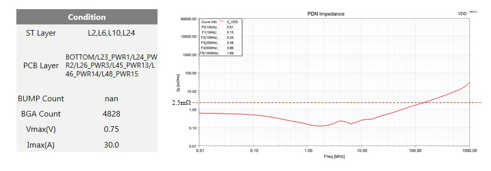
Simulation Condition: Needle + ST + PCB
|
Power Plane Name |
F0(10kHz) |
F1(1MHz) |
F2(10MHz) |
F3(25MHz) |
F4(50MHz) |
F5(100MHz) |
|
VDD |
0.61 |
0.15 |
0.25 |
0.46 |
0.86 |
1.69 |
- Copyright © 2016 Chunghwa Precision Test Tech.Co., Ltd . All rights reserved.
- 中華精測科技股份有限公司 著作權所有